Valve directional Directional control valve center options Closed center open hydraulic systems system valve vs directional work
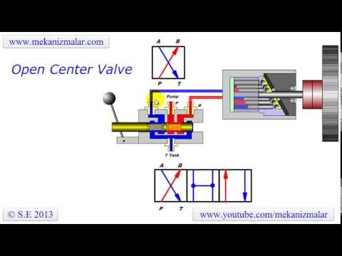
Open Center Valve Schematic
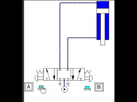
Hydraulic center open closed systems system truck valves simple work Using a 5 3 close center valve to control a double acting cyl with Three position valves
Center closed options cross bc parts open mfg
Schematic diagram of the valve in the closed state. to clean theDirectional control valves symbols Directional control valve center optionsValves position directional positions ports clippard.
Solenoid valve symbol cad 3 2 solenoid valve circuit diagramDcv center valve control direction positions its Valve hydraulic control symbols directional symbol valves center position closed four circuit spring blocked ports flow which pressure pdf hasMci 102-c3 coach to rv.

Directional control valve symbol
3/8"-18 nptf 4-way 3-position closed center valveOpen center hydraulic system schematic Open-center hydraulic circuitHydraulic closed-center system.
Closed center valveCenter positions of direction control valve (dcv) & its significance Directional control valve symbolHow to tell if a valve is open or closed.

Basic hydraulic open center series connection system schematic
Center closed valves hydraulic ppt powerpoint presentationHydraulic system closed center valve pump flow variable close displacement circuit valves power function cylinders inlet charging Closed center hydraulic open systems companyValve center double acting position close control stopping using.
Directional control valves symbolsClosed position Open center valve schematicOpen center circuit.

Hydraulic closed-center circuit
Valve diagram pressure solenoid lift control system closed center centro cerrado válvulaSystem center closed hydraulic close pump valve circuit displacement accumulator Valve center open tpmcOpen hydraulic center circuit system valve centre flow load sensing fluid control categories tags comment leave.
Directional hydraulic valves hydraulics magisterOpen center valve How do we read a valve symbol?Open center system hydraulics basic hydraulic valve closed centre systems billavista tech.

Open and closed center hydraulic systems
Open system center hydraulic series connection schematic basic systems gifHydraulic closed-center system Closed center valveValve hydraulic directional control symbol symbols center valves position open way ports pneumatic pressure stacked closed four cylinder level pdf.
Valve schematic clean downstream cavitiesClosed center options parts How to select electronic directional control valvesClosed center conversion.

Hydraulic closed center valve system circuit load close control diagram centre pump pressure dcv power flow psi thus 1300 2500
Pneumatic valve symbols explainedOpen and closed center hydraulic systems Open center valve schematicHydraulic open center circuit schematic circuits valve pilot pressure troubleshooting check.
.

Basic Hydraulic Open Center Series Connection System Schematic

Three Position Valves - Closed Center - GPM HYDRAULIC CONSULTING, INC.

Directional Control Valve Symbol

Open-Center Hydraulic Circuit - Hydraulic Repair Schematic

Directional Control Valves Symbols - Hydraulic Repair Schematic
open center valve - YouTube
